Guide
Our story at Thermo Electric began nearly 60 years ago with a singular, critical challenge: accurately measuring exhaust gas temperatures in aeroplane engines. This environment, characterized by extreme temperatures, intense vibration, and the absolute necessity for reliability, is what our engineering philosophy is built on. Today, we apply the lessons learned from that demanding context to every temperature sensor we design and manufacture for your industrial processes. Whether you are working in petrochemicals, power generation, semiconductors or pharmaceuticals, we understand that you face similar challenges where measurement accuracy and durability are not just operational goals, but foundational requirements for safety and efficiency.
When we talk about the engineering of temperature sensor assemblies, we are referring to a multi-faceted approach. It begins with meticulous material selection, ensuring that every component, from the thermocouple alloys to the outer sheath, is perfectly matched to the application’s chemical and thermal demands. It extends to our design process, where we consider factors like mechanical stress, vibrational harmonics, and thermal expansion to ensure our sensors survive and perform long-term in your plant. Our commitment to this philosophy is not just a statement; it is a documented and audited process. Our quality management system is certified to the ISO 9001:2015 standard, which provides you with the assurance of complete traceability and consistent manufacturing. Also, our adherence to the ISO 14001:2015 environmental standard reflects our responsibility as a modern manufacturer. Providing you with a reliable sensor assembly means delivering a product born from engineering excellence, built with discipline, and supported by a transparent quality framework.
A Technical Overview of Our Sensor Technologies
As engineers and technicians, you know that selecting the right tool for the job is the first step toward a successful outcome. This section provides a deeper look into temperature principles to help you make informed decisions. Please remember that all our sensors are sensitive instruments. To ensure their integrity, your safety, and the validity of the measurement data, installation must be performed by trained personnel who have thoroughly reviewed and understood the complete operating instructions.
Thermocouples
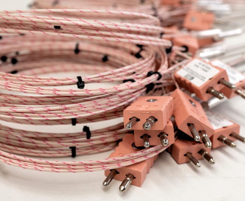
Our thermocouples function on a fundamental principle of physics known as the Seebeck effect. When two different conductive metals are joined at a point (the “measuring junction”), a small, open-circuit voltage is produced that is directly proportional to the temperature difference between that junction and the other end of the wires (the “reference junction”). By precisely measuring this millivolt-level signal and compensating for the known temperature at the reference end (typically within your instrumentation), we can accurately determine the process temperature.
Understanding Our Junction Types:
The construction of the measuring junction is a critical design choice that impacts performance. We offer several types to meet specific application needs:
- Grounded Junction: In this design, the thermocouple wires are physically welded to the tip of the protective sheath. This direct contact provides a superior path for thermal energy, resulting in a significantly faster response time. This makes it the most common type and our recommendation for most applications where rapid detection of temperature changes is important. The primary consideration for engineers is that this creates an electrical connection between the process and the instrumentation, which can introduce ground loop noise in electrically active environments.
- Insulated Junction: Here, the thermocouple wires are welded together but are electrically isolated from the protective sheath by a layer of mineral insulation (MgO). While this thermal barrier results in a slower response time compared to a grounded junction, it is essential for applications requiring electrical isolation. We recommend this type when measuring in conductive solutions, in processes with high electrical noise, or where connecting multiple thermocouples to a single instrument could create unwanted measurement paths.
- Exposed Loop: This design offers the fastest possible response by placing the welded junction directly in the process stream with no protective sheath at the very tip. Its use is limited to non-corrosive, low-pressure applications, such as measuring clean gas temperatures. The junction is vulnerable to mechanical damage and chemical contamination, so we advise its use primarily for testing or in carefully controlled environments.
- Duplex and Reduced Tip Models: To provide further flexibility, we construct duplex assemblies containing two independent junctions within a single sensor body, ideal for redundant measurement or control and monitoring. We also offer reduced-diameter tips on both grounded and insulated models to accelerate response times for specific measurement points.
A Note on Accuracy and Long-Term Stability:
Our thermocouples are manufactured to meet the accuracy classes defined by standards like IEC 60584-1 and ASTM E230. However, all thermocouples can experience “drift” over their operational life, which is the gradual loss of accuracy. This can be caused by the high-temperature oxidation or chemical contamination of the thermocouple alloys. For instance, in an ethylene furnace application cycling between 200°C and 850°C, a Type K thermocouple can drift by as much as 30°C within a year. A drift of this magnitude can have serious consequences for process efficiency and safety. This is why proper sensor selection, including the sheath material which provides the primary barrier against contamination, is a critical engineering decision.
Resistance Temperature Detectors (RTDs)
Our RTDs operate on the principle of thermo-resistance: the electrical resistance of a metal changes in a highly predictable and repeatable manner with temperature. For applications below 500°C, we recommend RTDs when your primary requirements are high accuracy, stability, and repeatability. The sensing element is typically a coil or film of high-purity platinum, chosen for its extremely stable and well-documented temperature-resistance relationship.
Wire Configurations Explained:
The resistance change in an RTD element is very small, so the resistance of the lead wires connecting the sensor to the instrument can introduce significant errors if not properly managed. We offer several configurations to address this:
- 2-Wire System: This is the simplest configuration, but the resistance of the lead wires is added to the resistance of the sensing element, introducing an inherent error. It is suitable only for applications where the lead wires are very short and high precision is not required.
- 3-Wire System: This is a significant improvement and a common industrial standard. The system uses a third wire to measure the resistance of one of the leads, assumes the leads are identical, and subtracts this value from the total measurement. This effectively cancels out most of the lead wire error.
- 4-Wire System: This configuration provides the highest possible measurement accuracy. It uses two wires to carry the excitation current and two separate wires to measure the voltage drop directly across the sensing element. Because virtually no current flows through the voltage-measuring leads, their resistance has no effect on the reading. This true Kelvin connection completely eliminates lead wire resistance as a source of error.
Key Performance Considerations:
Our Pt100 RTDs, which exhibit 100 ohms of resistance at 0°C, are manufactured to meet the accuracy tolerances of IEC 60751. It is important for you as the system designer to be aware that different global standards exist, such as the American (ANSI) and Japanese (JIS) standards, which specify slightly different alpha values (resistance change per degree Celsius). Mismatching the sensor type to the instrumentation’s expected input can lead to systemic measurement errors.
Additionally, RTDs require a small excitation current to measure their resistance. This current causes minor self-heating (I²R heating). To ensure this does not affect the measurement, we strongly recommend keeping the current at or below 1 mA.
Installation and Mounting Guidelines for Optimal Performance
A properly installed sensor is essential for accurate measurement. The following guidelines are based on our experience and are intended to help you avoid common installation pitfalls.
- Achieving Correct Insertion Depth: The most common source of measurement error is insufficient immersion, which leads to “stem conduction.” This occurs when heat is conducted along the sensor’s sheath away from the tip, causing the measuring junction to be at a different temperature than the process fluid. To prevent this, we have established a clear guideline: ensure the sensor is inserted a minimum of 7 times its protective tube diameter into liquids, and 13 times its diameter into gases. Installing the sensor at a pipe bend or in an oblique orientation against the flow can also help ensure the tip is measuring the true process temperature.
- Mounting and Assembly: All our sensor assemblies must be mounted securely and in a pressure-tight manner. For elements installed within our thermowells, it is critical that the element is spring-loaded. This ensures that the tip of the sensor maintains positive contact with the bottom of the thermowell bore, guaranteeing good thermal transfer.
Specific Welding Procedures for Technicians:
Proper welding is critical not only for a secure mount but also for the long-term health of the sensor. Poor technique can create stress points or damage the sheath.
- For Our Tube Skin Thermocouples: After preparing the tube surface, weld the tube clip using a single pass fillet weld on the ends only. Then, weld the heatshield over the thermocouple on three sides, taking care to retain the refractory material inside the shield, as it is crucial for accurate skin temperature measurement.
- For Our Knife Edge Thermocouples: After cleaning the tube and weld pad, weld the pad to the tube surface on three sides. Position the thermocouple and then weld the retaining clip to both the pad and the heater tube. A critical note: The thermocouple sheath must never be bent to a radius smaller than 3 times its own diameter. Any attempt to bend the knife edge itself will damage the sensor. For applications with significant thermal expansion, we recommend welding an expansion loop to the tube to provide strain relief.
Safety, Compliance, and Proactive Maintenance
Operating safely in industrial environments is a shared responsibility. We design and certify our products for hazardous locations, and you are responsible for their correct application and installation. Our sensors carry ATEX and IECEx approvals for various protection types, including Intrinsic Safety (Ex ia/ib), which limits electrical energy to prevent ignition, and Flameproof Enclosure (Ex db), which contains any potential internal explosion.
Key Safety and Compliance Requirements:
- IP Rating: Ensure the entire assembly, including the connection head, maintains at least an IP54 rating (or higher as specified by the certification, e.g., IP66/67 for Ex db) to protect against dust and moisture ingress.
- Cables and Glands: You must use cables and glands that are certified for the specific hazardous area classification. In high-temperature areas, use cables rated for at least 90°C.
- Temperature Verification: As the end user, you must verify that the process temperature does not cause the connection head’s surface temperature to exceed the limit specified by the T-rating (e.g., T6 specifies a maximum surface temperature of 85°C).
Recommended Maintenance Checks:
A proactive maintenance schedule is the best way to ensure continued reliability. We recommend regularly checking the entire measuring circuit for:
- Protective tube wear: Physical erosion or corrosion can compromise the process boundary.
- Element drift: Use a calibrated reference to check for loss of accuracy.
- Low insulation resistance: Moisture or contamination can cause short circuits and measurement errors. The resistance should always be >1 MΩ.
- Damaged connections: Check for loose terminals or corrosion.
Essential Documentation for Engineers: The MDR and IOM Manual
We believe that a high-quality instrument is accompanied by high-quality documentation. For every sensor we provide, the Installation, Operation, and Maintenance (IOM) manual and the Manufacturer’s Data Record (MDR) are critical documents. They are designed to support you throughout the entire lifecycle of the product, from receiving and installation to commissioning and eventual replacement.
The IOM: Your Operational Handbook
We view our IOM manual not as a simple instruction booklet, but as the comprehensive operational guide for your sensor. For engineers and technicians, it is the primary resource for ensuring a successful and safe installation. Adherence to the procedures within the IOM is essential for compliance, especially in hazardous environments where incorrect installation can invalidate an ATEX or IECEx certification.
Inside the IOM, you will find all the practical, technical details needed to do your job correctly. This includes step-by-step mounting instructions, wiring diagrams illustrating correct polarity, and the preventative maintenance checks required to ensure long-term reliability. The IOM is your go-to reference for getting the sensor commissioned safely and efficiently.
The MDR: Your Guarantee of Traceability and Quality
Complementing the IOM is the Manufacturer’s Data Record (MDR). Think of the MDR as your sensor’s official passport, providing complete traceability and a detailed history of its creation. For any engineer involved in quality assurance, process safety, or asset management, this document is invaluable. It provides the auditable proof that the product you received was built and tested to the exact specifications you ordered.
The MDR is your key to unlocking a wealth of engineering data specific to your sensor’s serial number, including:
- Complete Traceability: It contains all relevant material certificates (e.g., EN 10204 3.1) for every wetted part. This allows you to verify, with certainty, the exact alloys used, which is critical for confirming chemical compatibility and mechanical integrity in your process.
- As-Built Data: The MDR includes the final “as-built” drawings and dimensions, along with manufacturing records such as Welding Procedure Specifications (WPS) and Procedure Qualification Records (PQR) for any welded components. This is essential data for your asset management system.
- Test and Calibration Results: We document the results of all quality checks, including pressure tests, helium leak tests, and functional performance tests. Most importantly, the MDR contains the unique calibration report for your specific sensor. This report serves as the baseline for the sensor’s performance, against which you can track its stability and drift over its service life.
- Consolidated Certifications: All applicable certifications, from hazardous area approvals (ATEX, IECEx, etc.) to quality system conformances, are listed in one place, tied directly to your product’s unique serial number.
Together, the IOM and MDR provide a complete documentation package that ensures compliance, simplifies installation, and assists you with the data needed to manage your critical temperature measurements effectively.
Wrapping Up
We trust this guide has provided you with valuable technical insights, reinforcing our commitment to being more than just a leading manufacturer of high-quality temperature sensors. Our goal is to be your technical partner for your projects when it comes to achieving high-quality, reliable, and fully traceable process control. We believe this starts with a shared understanding that every step, from selection and installation to maintenance and documentation, is critical for a safe and reliable measurement loop.
The integrity of your data and the safety of your operations are as important to us as they are to you. While this guide serves as a foundation, we know every application has unique complexities, and we encourage you to contact us with any further questions. Our team of experienced engineers is ready to provide the expert support you need to solve your most demanding temperature measurement challenges.