RTDs
Precise temperature control is critical in sectors ranging from chemical production to semiconductor fabrication. Resistance Temperature Detectors, RTDs for short, provide the high accuracy and repeatability required for these demanding services. This guide reviews RTD fundamentals, construction styles, accuracy classes, stability considerations, and advanced calibration techniques that help engineers extract maximum performance from every installation.
Operating principle
RTDs rely on the predictable change of electrical resistance with temperature that occurs in certain metals. Measure the element resistance and, using a known resistance‑temperature relationship, calculate the temperature. Platinum is the preferred material because it offers high chemical stability, near‑linear response, and repeatable behaviour over a wide range.
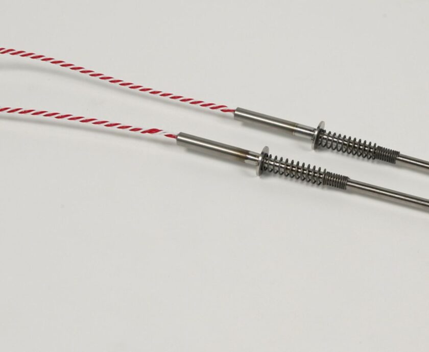
Sensor construction
Style | Typical range | Strengths | Limitations |
Wire‑wound (mandrel, helical, or coil‑suspension) | −200 to +850 °C standard, up to 960 °C with special curves | Wide span, excellent long‑term stability | Larger mass, more vulnerable to vibration |
Thin‑film | −200 to +800 °C | Fast response, high vibration tolerance, lower cost | Narrower span, slightly higher hysteresis |
Both styles are housed in metal sheaths (usually 316 SS, Inconel, or Hastelloy), packed with MgO to insulate the element and leads. Single or dual elements may be specified when hot backup or drift monitoring is required.
Accuracy and standards
The IEC 60751 standard defines the ideal resistance curve, a common alpha value of 0.00385 Ω/Ω/°C, and two tolerance classes.
- Class A ±(0.15 + 0.002 |t|) °C
- Class B ±(0.30 + 0.005 |t|) °C
A high‑quality transmitter typically adds only ±0.1 °C, so sensor tolerance dominates the system error unless further trimmed with sensor matching.
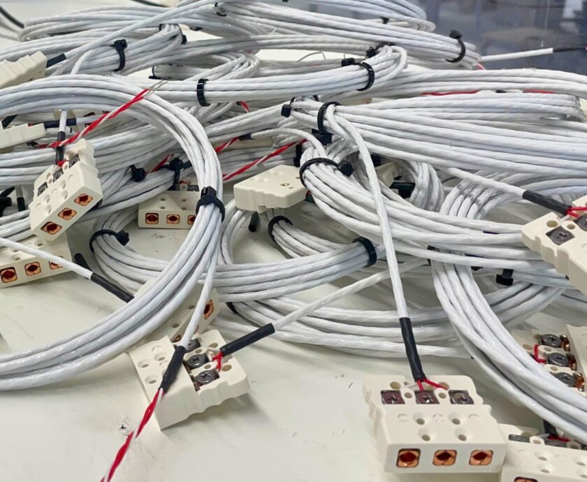
Lead‑wire configurations
Wires | Compensation method | Typical use |
Two | None | Rare in the industry due to the wire‑resistance error |
Three | Third lead assumes equal resistance, partial compensation | General purpose, moderate accuracy |
Four | Constant current through one pair, voltage sensed on the other, eliminates lead resistance | High‑accuracy loops, long cable runs |
Choose four‑wire whenever practical, especially for precision control or long field cables.
Stability and drift
Accurate resistance temperature detector sensors drift slowly, often less than 0.05 °C per year under moderate conditions. Drift rises with temperature and mechanical strain. Wire‑wound sensors usually show lower hysteresis and drift than thin‑film equivalents, though thin‑film’s ruggedness makes it ideal for high vibration. Small self‑heating errors are minimised by transmitters that drive currents below 250 µA.
Specification checklist
- Choose element style: wire‑wound for highest accuracy and span, thin‑film for rugged fast response.
- Select tolerance class: Class A for tight control, Class B when standard accuracy suffices, or use CVD matching for best‑in‑class accuracy.
- Match lead configuration: default to four‑wire unless plant standards dictate otherwise.
- Pick a sheath alloy: base selection on corrosion, temperature, and mechanical demands.
- Consider dual elements when redundancy or drift monitoring is required.
Wrapping Up
Industrial-grade resistance thermometer detectors deliver unrivalled accuracy and stability for industrial temperature measurement when their design is matched to process conditions, wiring practices minimise error, and smart transmitters exploit sensor‑specific calibration. Follow the guidelines in this document, and your RTD loops will provide the reliable data needed for safe and efficient plant operation.