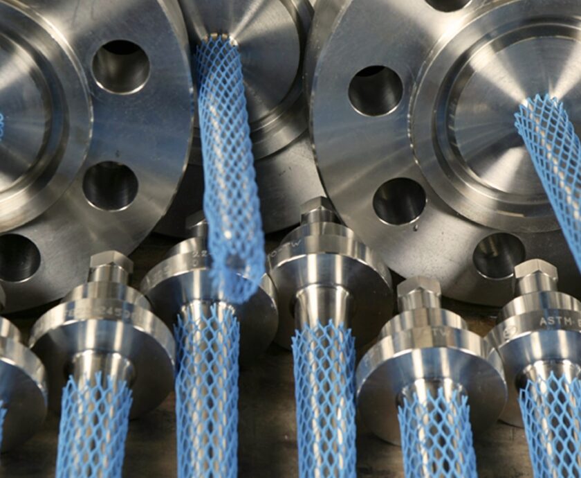
Thermowells
Imagine trying to take the temperature of a volatile fluid moving at high speed through a pipeline. Sticking a standard sensor directly into that flow is a recipe for disaster; the pressure and fluid flow would destroy it. This is the challenge where the thermowell proves its worth.
Acting as a permanent, rugged barrier, a Thermowell creates a safe pocket for the delicate sensor. But this protection introduces a new set of engineering challenges: a poorly designed thermowell can give sluggish readings, or worse, resonate with the flow until it snaps, causing a catastrophic failure. The ASME PTC 19.3 TW-2016 standard offers a thorough framework for thermowell mechanical design and performance evaluation. This article explores how these factors impact thermowell performance.
Response Time Considerations
Response time is the measure of how quickly a temperature system reflects process temperature changes. Although sensors have inherent response times, thermowells add thermal mass, slowing the overall system response due to the heat transfer required from the process fluid through the thermowell and fill material to the sensor.
Key factors influencing response time include:
- Thermal Mass: Reducing thermowell mass accelerates response but must maintain structural integrity.
- Stem Style: Profiles with smaller tip mass respond more quickly.
- Tip Thickness and Diameter: Smaller tips reduce thermal lag.
- Sensor Fit: A snug, full-length sensor-to-bore fit minimizes air gaps, enhancing conduction.
- Spring-Loaded Sensors: These ensure contact between the sensor and bore bottom, reducing thermal resistance.
- Thermal Fill: Conductive materials improve heat transfer.
- Process Media: Faster, denser fluids improve heat transfer.
- Insertion Length: Proper depth, ideally near the pipe or vessel centerline, ensures exposure to representative temperatures.
ASTM E 839-89 outlines standard methods for response time testing using liquid baths.
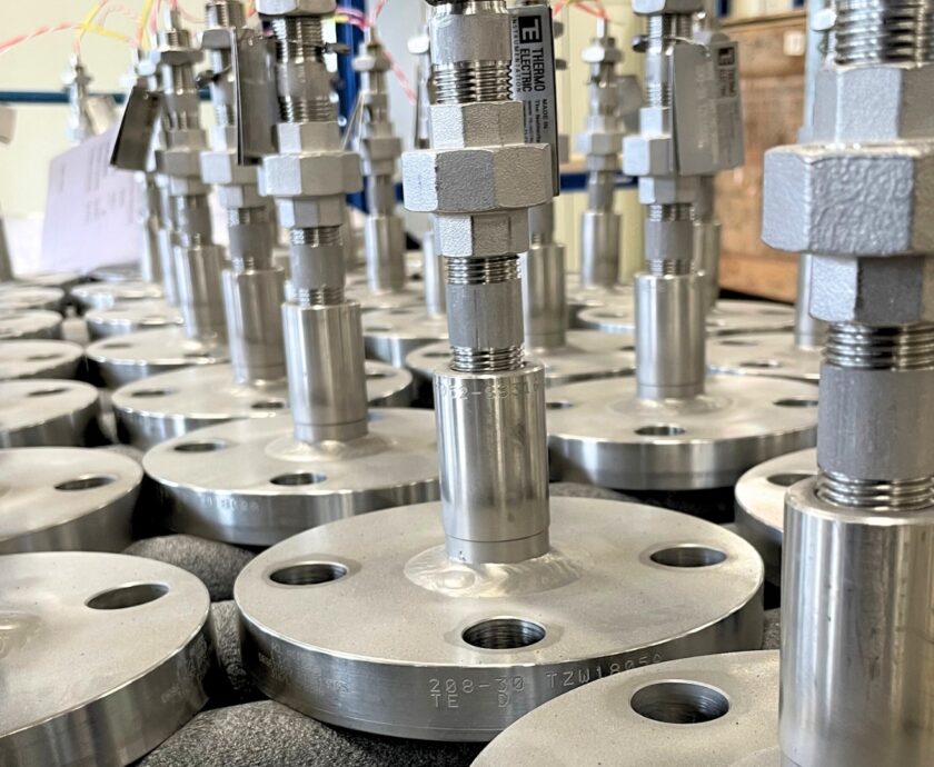
Thermowell Stem Profiles
The stem, or shank, is the inserted portion of a thermowell. Its profile affects pressure rating, response time, and vibration resistance. Common types include:
- Straight Profile: Constant diameter, slowest response due to high mass, highest pressure rating, most drag force.
- Stepped Profile: Reduced tip diameter lowers mass and drag, resulting in faster response and higher natural frequency. Typically has lower pressure ratings.
- Tapered Profile: Diameter decreases from root to tip, balancing strength, response, and drag. Suitable for high-velocity flow.
- Helical Strake: A unique design to suppress vortex-induced vibration (VIV). It enhances immersion depth while minimizing vibration, suitable for high-velocity gas/steam and multiphase flows. Although not currently within ASME PTC 19.3 TW-2016 scope.
Vibration Considerations
As fluid flows around a thermowell, vortices form on the downstream side, causing alternating forces that can lead to VIV. When the vortex shedding frequency (Strouhal frequency) aligns with the thermowell’s natural frequency, resonance occurs, risking fatigue failure.
ASME PTC 19.3 TW-2016 addresses these dynamics through:
- Frequency Limit: Avoiding both transverse and in-line resonance conditions.
- Dynamic Stress Limit: Ensuring oscillating stresses stay below fatigue limits.
- Static Stress Limit: Managing steady-state stresses.
- Hydrostatic Pressure Limit: Confirming pressure ratings across components.
Wake frequency calculations assess resonance risk based on process conditions and thermowell geometry. Tools like the Thermo Electic Thermowell Design Checker assist with this.
Mitigating Vibration Risks
- Stem Profile: Stepped and Helical strake designs increase the natural frequency and suppress VIV.
- Design Adjustments: Shorter unsupported length, larger support diameter, and smaller tip diameter help manage stress.
- Velocity Management: Avoid operating at critical resonance speeds, although transient exposure is sometimes permitted.
- Scruton Number: Indicates damping capacity; values above 2.5 are favorable.
- Material Selection: Use corrosion-resistant and fatigue-tolerant materials.
Vibration sources not fully covered by ASME include turbulence-induced and pulsed flow vibrations, and structure-borne vibrations from piping systems.
Wrapping Up
Thermowell optimization is a balance of thermal response, structural integrity, and vibration resistance. The stem profile is a major determinant of performance. Stepped and tapered designs offer faster response and improved vibration resistance whilst the Helical strake profile specifically targets VIV reduction.
Using ASME PTC 19.3 TW-2016 and modern design tools ensures thermowells meet performance and safety standards. Proper front-end engineering results in systems with lower lifecycle costs and greater reliability.